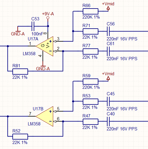
Creating A Balanced Line Output
From an unbalanced line level signal

Converting Balanced Line Level to Un-Balanced

NOTE: The 22K resistors used here work great, but 22K can cause noise to be picked up from close digital tracks (e.g. 3.3V clock signals). We discovered just such a problem on a digital PCB causing pickup to occur at the negative op amp input and the remedy was to change to 2K resistors instead.

USEFUL?
We benefit hugely from resources on the web so we decided we should try and give back some of our knowledge and resources to the community by opening up many of our company’s internal notes and libraries through resources like this. We hope you find it helpful.
Please feel free to comment if you can add help to this page or point out issues and solutions you have found, but please note that we do not provide support here. If you need help with a problem please use one of the many online forums.

