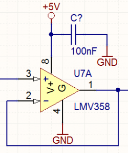
Voltage Follower

Also called a buffer. Only the OpAmp tiny bias current is drawn from the signal source.
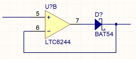
Voltage follower with output diode drop removal

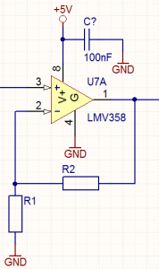
Non Inverting Amplifier

Vout = Vin x (1 + (R2/R1))
E.g. R1=10k, R2=10K, Vin=1V, Vout=2V
Only the OpAmp tiny bias current is drawn from the signal source.
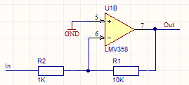
Inverting Amplifier

The input impedance is equal to the value of R2
The voltage gain is R1/R2 (a gain of 10). This configuration can also give negative gain (loss). If R2 is larger than R1 (say 20k), then the gain is equal to R1/R2 as before, so it would be -0.5.
THE INPUT TO THE INVERTING CONFIGURATION IS NOT HIGH IMPEDANCE!!! The OpAmp will do whatever is necessary to make the – input match the + input, meaning that when you measure the – input with a scope it will be at 0V. Say you have a +1V source signal in the circuit above, this means that 1V is being dropped over R2, which means a 1mA current is flowing. For that to happen and for the rule that OpAmp inputs draw no current to be true that same current is also passing through R1 which will be because the OpAmp is driving its output to -10V for that to happen. If this current being drawn from the source is a problem you can simply use a OpAmp follower before it or just use a non inverting amplifier configuration. This current flow and the – input measuring as 0V is a classic confusion for OpAmp newbies – once you realise why all OpAmp circuits become much simpler to understand.

